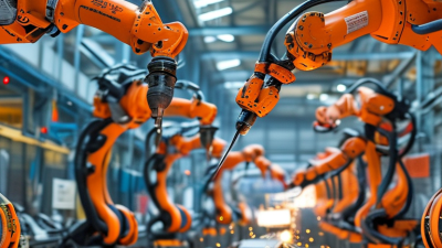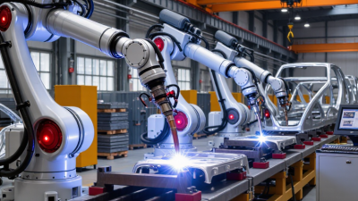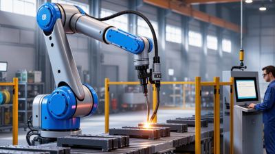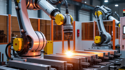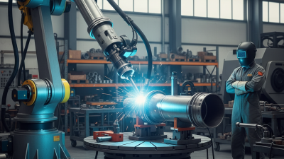
In 2026, choosing a robotic welding system means matching the cell to production—not chasing the fastest arm. A system that excels on a clean sample part may struggle with a warped bracket, changing joint gaps, or short runs. Those details decide whether automation earns its place on the floor.
This guide explains how to assess part mix, weld process, reach, payload, fixtures, and expected cycle time. Start with actual drawings and representative parts; record material thickness, joint access, batch size, and rework patterns. A demo weld should use your components, wire, and fixture whenever possible. Watch the arc, but also note load time, changeover steps, fume extraction, and how easily operators can recover from a fault. Small interruptions add up.
Consider whether the cell can handle the next product family without extensive retooling. Offline programming can reduce setup delays, but it depends on accurate models and disciplined process data. Ask for measured results, not a brochure cycle time. Real production is rarely as tidy. The right choice also depends on integration and support. Check how the robot, power source, positioner, torch, and safety equipment work together, then ask who will maintain them and train staff. Compare total operating costs, including consumables, programming, downtime, and spare parts—not just the quoted cell price. No checklist predicts every production surprise. Not always. A supplier’s confident estimate still deserves a trial and careful review. This article offers a practical framework for choosing robotic welding equipment in 2026, with trade-offs made visible before installation.
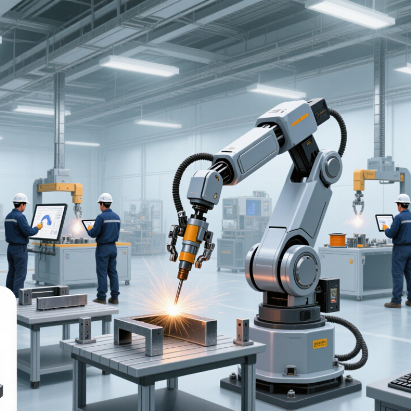
Define the weld before comparing robot reach or payload. Record the process, wire or electrode, shielding gas, material grade, thickness, and surface condition. A 3 mm mild-steel fillet weld differs sharply from a thick aluminum butt joint. Joint access matters too: note the root gap, torch angle, weld position, and whether fixtures can repeatably hold parts. Small details matter. The International Federation of Robotics’ World Robotics 2024 report counted 541,302 industrial robots installed worldwide in 2023. That scale shows automation is established, but it does not mean every weld suits a robot.
Map the production mix honestly. List annual volume, part-family sizes, changeover frequency, and the share of rework. A cell built for one long seam may struggle with short, scattered welds across frequent variants. Ask operators to trial actual parts, including imperfect fit-up and spatter-prone edges. These are often where a tidy simulation meets shop-floor reality. The American Welding Society’s workforce outlook projects 360,000 welding professionals will be needed by 2027; labor pressure may support automation, but it cannot replace process validation. Compare candidate systems using sample welds, measured cycle times, and destructive or nondestructive inspection results. Keep the assumptions visible.
| Decision dimension | What to define | Typical options or conditions | Implications for system selection |
|---|---|---|---|
| Welding process | Required process, weld size, position, quality level, and deposition needs. | GMAW (MIG/MAG) is widely used for production welding; GTAW (TIG) is often chosen when precise heat input and a clean weld are important; resistance spot welding is common for overlapping sheet-metal joints; laser welding can suit accessible joints requiring a narrow, concentrated heat input. | Match the power source, torch or gun, wire or electrode feeding, process controls, and safety measures to the selected process. Confirm that the process can meet the applicable weld procedure and acceptance requirements. |
| Base materials | Material grade, thickness range, coatings, surface condition, and material combinations. | Common applications include carbon steel, stainless steel, and aluminum. Aluminum and stainless steel can require different consumables and process settings from carbon steel. Coatings, such as zinc, can affect fume generation and weld preparation. | Check process compatibility, consumable selection, shielding-gas requirements, fixture contact, fume extraction, and the need for cleaning or coating removal. Validate the full thickness and material range with representative samples. |
| Joint geometry | Joint type, seam length, access, fit-up variation, weld position, and required torch approach. | Typical joints include fillet, butt, lap, and plug welds. Narrow gaps, variable part location, corners, and restricted access can make seam tracking or repositioning more important. | Assess robot reach, torch angle, cable routing, workpiece rotation, fixture access, and collision risk. Consider touch sensing, through-arc sensing, or vision-based tracking when part or seam variation exceeds the capability of a fixed programmed path. |
| Part and seam variation | Repeatability of part location, gap size, edge preparation, and assembly fit-up. | Consistent, accurately fixtured parts can support fixed-path welding. Greater variation may call for sensing, adaptive parameters, improved fixturing, or upstream process control. | Measure actual variation before choosing sensing features. Sensors can help locate a seam but do not replace sound joint preparation, stable fixturing, or a qualified welding procedure. |
| Production mix | Annual volume, number of part variants, batch size, changeover frequency, and expected product changes. | Long runs of a small number of parts favor dedicated fixtures and optimized cycle sequences. High-mix, lower-volume work benefits from accessible reprogramming, repeatable setup methods, and flexible workholding. | Compare time spent welding with loading, unloading, repositioning, and changeover. Include programming effort and fixture cost when estimating capacity and payback. |
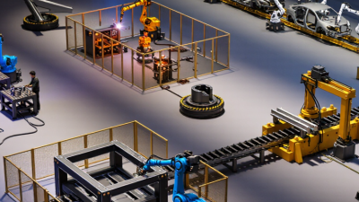
| Part size and cell layout | Workpiece dimensions and weight, number of weld locations, operator access, and available floor space. | A single-station cell may suit compact parts and simple workflows. Larger parts or multiple weld faces may require a positioner, multi-station arrangement, or a robot mounted on a track. | Verify reach throughout the complete work envelope, payload, positioner capacity, loading access, guarding, and maintenance access. Confirm that the chosen layout supports safe part handling. |
| Quality and inspection | Applicable codes or customer specifications, visual criteria, inspection method, traceability, and documentation needs. | Requirements vary by product and application. Inspection may include visual checks and, where specified, non-destructive testing or recorded process data. | Define acceptance criteria before system design. Plan for weld procedure qualification, operator and maintenance training, inspection access, and data records where required. |
| Cycle time and uptime | Required output, arc-on time, loading time, shift pattern, and planned maintenance availability. | Total cycle time includes more than arc time: part handling, clamping, repositioning, inspection, and changeovers also contribute. | Use a representative production trial to validate throughput. Include consumable changes, torch cleaning, tip or nozzle replacement, and recovery from faults in the capacity estimate. |
| Safety and workplace conditions | Welding hazards, operator tasks, cell access, fume levels, and applicable safety requirements. | Arc radiation, hot work, moving equipment, electrical hazards, and welding fumes need appropriate controls. The required measures depend on the process and work environment. | Include risk assessment, guarding or presence-sensing measures, interlocks, emergency stops, ventilation, and safe loading procedures in the cell design. Verify local regulatory requirements. |
| Practical validation | Representative parts, production conditions, and measurable acceptance criteria. | A trial should cover the intended material range, joint types, fit-up variation, and expected production sequence. | Before final selection, confirm weld quality, cycle time, changeover process, accessibility, and operator workflow using test parts and documented procedures. |