How to Choose the Best Robotic Welding Systems?

Robotic welding systems are attracting attention as manufacturers seek steadier output, repeatable welds, and relief from difficult manual tasks. The International Federation of Robotics reported 541,302 industrial robot installations worldwide in 2023, bringing the operating stock to about 4.28 million units. These figures, published in World Robotics 2024, show broad industrial adoption. They do not reveal how many robots suit a particular welding cell. That distinction matters.

Choosing a system starts with the actual job. A robot that handles long, consistent seams may struggle with short runs, frequent changeovers, or parts that vary slightly from fixture to fixture. Buyers should compare payload, reach, torch access, positioner capacity, programming tools, guarding, and integration support. They should also ask how the system will be maintained and whether operators can adjust it without waiting for a specialist. Small details count. A torch neck that cannot reach a joint can undermine an otherwise impressive specification sheet.

Production volume, material, joint design, and available floor space all shape the decision. So do consumables, downtime, training, and the cost of adapting existing equipment. There is no universal “best” system; even a careful shortlist can miss an awkward part or a maintenance constraint. Use supplier demonstrations with representative workpieces, and request measured cycle times rather than broad promises. The right choice is the one that fits the process reliably, not simply the one with the most advanced features.
How to Choose the Best Robotic Welding Systems?

Define the Welding Tasks, Materials, and Production Requirements

Before comparing robotic welding systems, define the weld, not just the part. Record the process, joint type, weld length, position, and acceptable appearance. Note the base metal, thickness, surface condition, and any coatings. A stainless-steel bracket and a thick carbon-steel frame demand different settings and access. Include fixture space and torch clearance; a robot cannot reach through a clamp. Small details matter.

Set production requirements with real numbers. State parts per shift, annual volume, batch size, changeover frequency, and target cycle time. Include inspection needs, data records, and how often operators can tend the cell. The International Federation of Robotics reported 541,302 industrial robot installations worldwide in 2023, across manufacturing sectors; this figure signals broad adoption, not welding-specific demand. (IFR, World Robotics 2024.) Use it as context, not as proof that automation suits every line. Run representative parts through a process trial, including awkward joints and planned changeovers. Measure rework, not just arc-on time. A polished demo part proves little. Specifications can still miss the messiness of a real shift, so leave room to revise them after operators test the workflow.

Match Robot Reach, Payload, and Motion Capabilities to the Workpieces

How to Choose the Best Robotic Welding Systems?

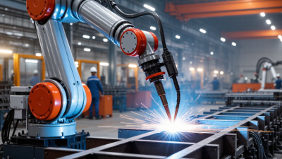
Match the robot’s reach, payload, and motion to the actual workpieces—not just the largest part on the drawing. Measure the full path around each joint, including torch angle and clearance beside clamps. A robot may reach a seam but still struggle to approach it cleanly. Check the work envelope with fixtures installed. Tight corners matter.

Payload calculations should include the welding torch, cables, brackets, and any added sensors. These components affect wrist load and movement, especially when the arm changes direction quickly. Also consider part size and weight: a positioner may move the workpiece, but it changes the motion requirements. It is easy to overlook cable routing. I would verify it in a real setup.

Tips: Test representative parts and fixtures before final selection. Watch for collisions, awkward torch angles, and slow transitions between seams. Ask the integrator to confirm payload and reach at the robot’s actual working positions, not only at maximum extension. Maximum reach can be misleading. If the part mix is still changing, leave room for adjustment; that may cost more upfront, but guessing too tightly can be harder to fix later.

Evaluate Welding Processes, Power Sources, and Control Systems

A robotic welding system should fit the joint, material, and production rhythm—not just the advertised speed. Start with the welding process. MIG/MAG suits many structural parts and can sustain high deposition rates. TIG offers cleaner control on thin sections, but usually moves more slowly. For a sample bracket, check penetration at the corners, spatter near clamps, and how often the torch needs cleaning. Small details matter.

The power source must match the process and the duty cycle. A unit that runs comfortably through short trials may struggle across a full shift. Ask how it handles current changes, wire feeding, and heat input on your actual material thickness. Controls matter just as much. The robot controller, welding source, and sensors should exchange signals reliably, while the interface lets operators adjust recipes without hunting through menus. Test seam tracking on parts with realistic variation, not only a perfect fixture. A tidy test cell can hide problems. I would also leave time for operator feedback; the first setup rarely feels right on the shop floor. Check recovery steps after a stopped arc, since awkward restarts can quietly consume production time.

How to Choose the Best Robotic Welding Systems? - Evaluate Welding Processes, Power Sources, and Control Systems

Evaluation Dimension Process or System Option Typical Characteristics Suitable Applications Key Selection Considerations
Welding process Gas metal arc welding (GMAW/MIG) Uses a continuously fed consumable wire electrode and shielding gas. Common power sources use constant-voltage output. Production welding of carbon steel, stainless steel, and aluminum parts where deposition rate and throughput matter. Check material thickness, joint access, wire-feed stability, spatter control, fume extraction, and the required shielding-gas arrangement.
Welding process Gas tungsten arc welding (GTAW/TIG) Uses a non-consumable tungsten electrode; filler metal may be added separately. Constant-current power sources are typical. Precision welds, thinner materials, and applications that require careful control of the weld pool. Generally has a lower deposition rate than GMAW. Assess cycle-time targets, torch access, filler-wire handling, and cleanliness requirements.
Welding process Laser beam welding Uses a concentrated laser beam. It can produce narrow welds with relatively low heat input, depending on material and process setup. High-speed joining of compatible parts with consistent joint geometry and suitable access for the beam and optics. Evaluate joint fit-up, material reflectivity and thickness, laser safety enclosure, beam delivery, and process monitoring needs.
Welding process Resistance spot welding Joins overlapping sheets using electrical current, electrode force, and resistance heating; filler metal and shielding gas are not normally used. Repeated spot joints in sheet-metal assemblies, including production lines with defined electrode access. Confirm sheet stack-up, electrode access and life, weld schedule control, cooling requirements, and the required current and force capacity.
Power source Constant-voltage arc source Commonly paired with wire-fed GMAW. Output voltage is regulated while welding current varies with wire-feed conditions. Robotic GMAW cells using a continuously fed wire electrode. Match the source to the process, duty cycle, material, wire-feed system, and required transfer modes. Verify communication with the robot controller.
Power source Constant-current arc source Commonly used for GTAW; it maintains current as arc voltage changes with arc length. Robotic TIG applications requiring controlled heat input and a stable arc. Check current range, pulse capability if needed, duty cycle, start method, and compatibility with the torch and robot interface.
Power source Laser source or resistance-welding supply Laser systems generate and deliver a focused beam; resistance systems provide controlled welding current and coordinate it with electrode force. Laser joining or resistance spot welding, respectively. Assess process-specific safety measures, energy capacity, cooling, maintenance access, monitoring, and integration with motion and safety controls.
Robot and motion control Robot controller with coordinated axes Controls programmed motion, speed, paths, and—where supported—external positioners or coordinated equipment. Parts with repeatable weld paths and production sequences. Review reach, payload, axis count, path repeatability, positioner coordination, programming workflow, and recovery after interruptions.
Process control Integrated weld-process control Coordinates robot motion with welding parameters such as current, voltage, wire feed, laser settings, or resistance-weld schedules. Applications needing consistent parameter control and traceable production settings. Confirm parameter adjustment methods, recipe management, alarms, data logging, and communication between the process equipment and robot.
Quality and sensing Seam finding, tracking, and weld monitoring Depending on the system, sensors can locate joints, compensate for part variation, or monitor selected process signals. Assemblies with variable fit-up, tight joint-location requirements, or production quality-record needs. Choose sensing based on the actual variation and inspection plan. Sensing and monitoring can support quality control but do not replace qualified procedures or required inspection.
Cell safety and serviceability Guarding, interlocks, extraction, and maintenance access Safety provisions depend on the process; laser cells require appropriate laser controls, while arc processes require protection from arc radiation and welding fumes. All automated welding cells. Include risk assessment, access interlocks, fume control, safe teach and recovery modes, consumable changes, and planned maintenance in the cell design.

Check Safety Features, Integration Needs, and Operator Training

A robotic welding system should fit the work cell, not just the production target. Inspect the guarding, interlocked access doors, emergency stops, and fume extraction around the actual weld area. Ask how the cell responds when a door opens or a sensor detects an obstruction. Safe stops and restart steps should be clear to every shift. Small details matter.

Integration starts with the parts moving into and out of the cell. Map the fixtures, conveyors, extraction equipment, and control signals before selecting a system. Confirm that weld schedules and fault messages can be exchanged with existing controls. A technically compatible robot can still create bottlenecks if operators must enter settings in two places. That gets missed.

Operator training should include more than programming a clean demonstration weld. Have operators practice loading parts, checking torch condition, responding to alarms, and recovering from a stopped cycle. Use real fixtures and sample parts, including one with a small fit-up variation. Training takes time. It may also reveal that a planned workflow is awkward. Record who can make routine adjustments and who handles maintenance or program changes, so responsibility stays clear when the cell is busy.

Compare Total Ownership Costs, Reliability, and Technical Support

The purchase price is only the visible part of a robotic welding system’s cost. Include fixtures, integration, safety equipment, operator training, consumables, and planned maintenance in your estimate. Count the whole shift. A cell that needs frequent adjustments can lose production time even when the robot itself is reliable. Ask suppliers to show how they calculated expected uptime and maintenance costs, then check those assumptions against your own shift schedule and part mix.

Reliability depends on more than a specification sheet. Review service intervals, spare-part availability, and the process for diagnosing faults. Ask what happens when a torch collision or sensor error stops the cell at 2 a.m. Technical support should have clear response times, practical troubleshooting steps, and trained staff who understand welding applications. Request a sample maintenance plan and confirm which tasks your team can perform. A short production trial can expose awkward programming or fixture changes before full deployment. Still, no trial perfectly predicts years of use; that uncertainty deserves a line in the budget. Compare systems using the same production assumptions, and keep a contingency for repairs or training that proves more demanding than expected.

Contact Us