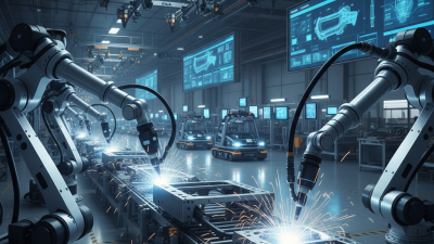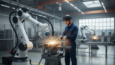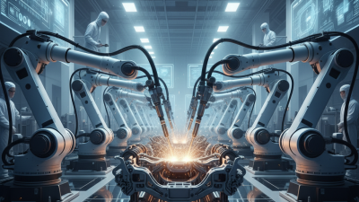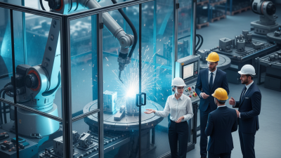
Robotic welding systems are no longer limited to large automotive factories. They now appear in structural steel shops, agricultural equipment plants, and contract manufacturing lines. Their purpose is practical: repeat a controlled weld, maintain stable torch movement, and reduce exposure to heat, fumes, and awkward postures.
The International Federation of Robotics reported 541,302 industrial robots installed worldwide in 2023. Its World Robotics 2024 report shows continued automation across manufacturing. Welding remains a major use because robots can repeat programmed paths with consistent speed and torch angle. MarketsandMarkets also identifies automotive, metals, and heavy machinery among important robotic welding applications. The numbers are encouraging. They are not a guarantee.
Henrik Christensen, a respected robotics researcher, once said, “A person using a robot will take your job.” The statement is uncomfortable, but useful. In welding, the robot does not replace process knowledge. Skilled technicians still select wire, gas flow, joint design, fixture position, and inspection methods. A robot can repeat a poor setup very accurately. That detail is often overlooked.
This guide explains what robotic welding systems contain, how sensors and controllers coordinate movement, and where automation creates measurable value. It also examines cycle time, weld quality, maintenance, programming skill, and worker safety. The picture is not perfect. Implementation can be expensive, integration can be slow, and reflective surfaces may confuse vision sensors. Reliable results require testing, documentation, and human judgment—not confident marketing language.
Sources: International Federation of Robotics, World Robotics 2024; MarketsandMarkets, Robotic Welding Market; Henrik Christensen, robotics research and automation commentary.
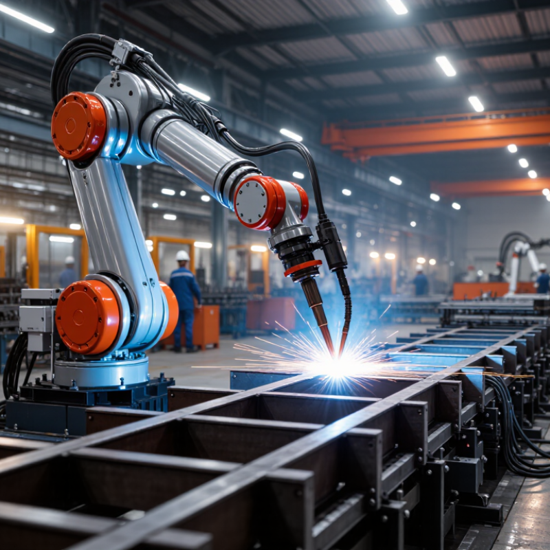
A robotic welding system is an integrated production cell, not merely a robot holding a torch. It combines a programmable robotic arm, welding power source, wire feeder, torch, fixtures, sensors, controller, and safety enclosure. The fixture keeps parts in a repeatable position. The controller then coordinates travel speed, torch angle, wire feed, and electrical output. That coordination creates consistent welds on repeated joints.
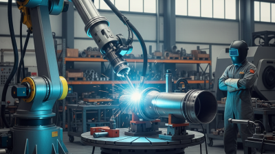
During operation, an operator loads the parts and selects a validated program. The robot moves along taught points while the welding arc deposits metal. Sensors can detect joint location, arc length, or part movement. A positioner may rotate the workpiece, keeping the weld pool stable. In practical cells, small setup errors matter. A dirty nozzle or loose fixture can quickly produce spatter, porosity, or missed joints.
The International Federation of Robotics reported 541,302 industrial robots installed worldwide in 2023. Its World Robotics 2024 report also recorded about 4.28 million robots operating globally. These figures show wider automation adoption, although they do not represent welding alone. Market research reports also forecast strong growth for robotic welding through the decade. Forecasts vary, and that is worth questioning. A robot does not automatically improve quality. Proper joint design, inspection, maintenance, and skilled programming still decide the result.
| Data Dimension | Description | Typical Data or Operating Information |
|---|---|---|
| Definition | A robotic welding system is an automated production cell that uses a programmable industrial robot to perform welding operations. | The system normally combines a robot, welding power source, torch, workholding equipment, sensors, safety devices, and a control system. |
| Primary Purpose | To produce consistent welds while reducing repetitive manual work and improving production efficiency. | Most suitable for repeated weld patterns, high production volumes, and parts with stable dimensions. |
| Industrial Robot | A multi-axis mechanical arm that moves the welding torch along a programmed path. | Six-axis articulated robots are widely used because they provide positional flexibility and access to multiple weld orientations. |
| Welding Process | The welding method is selected according to the material, joint design, thickness, and required weld quality. | Common processes include gas metal arc welding, gas tungsten arc welding, resistance spot welding, and laser welding. |
| Welding Torch | The torch delivers the welding current, shielding gas, and filler material when required. | Torch angle, travel speed, wire-feed rate, and contact-tip-to-work distance are programmed or controlled during welding. |
| Robot Controller | The controller coordinates robot motion, welding parameters, sensors, and peripheral equipment. | It stores welding programs and controls the sequence, speed, position, and timing of the operation. |
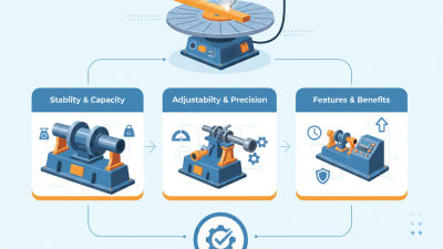
| Workholding System | Fixtures or positioners hold and orient the workpiece during welding. | A rigid fixture helps maintain joint alignment and reduces dimensional variation between parts. |
| Sensors and Tracking | Sensors can detect joint location, part position, arc conditions, or welding defects. | Typical technologies include touch sensing, through-arc seam tracking, vision systems, and weld-current monitoring. |
| Programming | An operator or welding engineer defines the robot path and welding parameters. | Programs specify travel points, approach and retract movements, welding speed, current, voltage, wire-feed rate, and gas flow. |
| Operating Sequence | The robot follows a repeatable sequence from part loading through welding and inspection. | Typical sequence: load part, clamp fixture, verify position, move torch, start arc, weld programmed path, stop arc, inspect, and unload. |
| Positioning Accuracy | Robot positioning performance affects weld placement and repeatability. | Many industrial welding robots provide repeatability in the approximate range of ±0.02 to ±0.10 mm, depending on model, payload, reach, and operating conditions. |
| Welding Speed | Travel speed determines how quickly the torch moves along the joint and influences penetration and bead appearance. | Arc travel speed varies widely by process and joint design; a typical automated arc-welding range is approximately 200–1,000 mm/min. |
| Payload Capacity | Payload is the maximum mass the robot can safely carry while maintaining its specified performance. | Welding robots commonly support payloads from approximately 5 kg to more than 20 kg, depending on the torch, cables, and application. |
| Cycle Time | Cycle time is the total time required to complete one programmed production cycle. | It includes loading, clamping, robot movement, arc time, repositioning, inspection, and unloading; actual time depends on the part and process. |
| Advantages | Automation can improve consistency, productivity, ergonomics, and process control. | Benefits may include repeatable weld geometry, reduced exposure to arc radiation and fumes, lower operator fatigue, and improved utilization. |
| Limitations | Robotic welding requires suitable parts, accurate fixtures, programming, maintenance, and trained personnel. | High initial investment, changeover time, part variation, fixture cost, and limited flexibility for low-volume mixed production can be challenges. |
| Safety Equipment | Safety systems protect personnel from moving equipment, welding arcs, heat, sparks, fumes, and electrical hazards. | Common safeguards include perimeter guarding, interlocked doors, emergency stops, light curtains, arc screens, fume extraction, and lockout procedures. |
| Quality Control | Quality control verifies that the weld meets the required design, dimensional, and inspection criteria. | Methods may include visual inspection, dimensional checks, weld-parameter monitoring, non-destructive testing, and periodic destructive testing. |
| Best-Fit Applications | Robotic welding is most effective when the workpiece and weld sequence are repeatable. | Typical applications include frames, structural assemblies, vehicle components, industrial equipment, containers, and fabricated metal parts. |