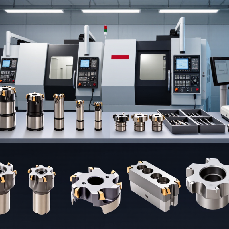
China Top Chamfering Cutter Manufacturer How to Choose?

Choosing a reliable China Top Chamfering Cutter Manufacturer requires more than comparing prices and product photos. A suitable supplier should understand your workpiece material, machine type, cutting angle, and production volume. Steel, aluminum, stainless steel, and composite materials demand different tool designs. The right Chamfering Cutter should produce a clean edge, stable dimensions, and minimal burrs during continuous machining. Small details matter. A rough finish may signal poor geometry, weak coating, or unsuitable cutting parameters.

Experienced manufacturers usually provide material recommendations, tolerance data, coating options, and application guidance. Ask for inspection records, sample reports, and clear drawings before placing a large order. Check whether the factory controls raw materials, heat treatment, grinding accuracy, and final inspection internally. A supplier with modern CNC equipment and skilled technicians can often maintain more consistent performance. Still, equipment alone proves little. Actual samples and customer feedback matter more.

Do not trust every claim.

A practical evaluation may include testing several cutters on your own machine. Record tool life, surface quality, vibration, and edge stability. Communication also reveals technical reliability. Can the manufacturer explain why one geometry suits your application? Can it respond clearly when a trial result is disappointing? No supplier is perfect, and an attractive catalog may hide limitations. I have seen buyers focus on unit cost, then lose time through unstable batches and delayed replacements. A dependable China manufacturer should offer transparent specifications, realistic delivery times, responsive support, and traceable quality control. Choose evidence over impressive language.

China Top Chamfering Cutter Manufacturer How to Choose?

Define the Job: Choose 45°, 60°, or 90° Angles and 0.1–3 mm Widths

Choosing a chamfering cutter starts with the drawing, not the tool catalog. Confirm whether the angle means the included angle or one cutting-face angle. This detail can change the finished profile. A 45° cutter suits common edge breaks and general deburring. It creates a balanced transition on many milled parts. A 60° cutter can provide more clearance where adjacent surfaces limit access. A 90° cutter is useful for specific countersink-style forms and pronounced edge transitions. Measure the edge.

Chamfer width matters just as much. Widths from 0.1 to 0.3 mm usually remove a sharp burr without noticeably changing the part profile. Widths around 0.5 to 1.5 mm create a clear, functional chamfer for handling or assembly. The 2 to 3 mm range needs enough stock, machine rigidity, and stable workholding. Otherwise, vibration may leave uneven marks. Check the drawing tolerance before selecting the width.

In practical machining, I once chose a wider chamfer to save a finishing pass. The cutter removed material quickly, but the thin component flexed. The result needed rework. That mistake still affects my selection process. I now test a small area first, especially on aluminum, hardened steel, or thin walls. Use a slower feed when the edge is delicate, but do not copy a generic setting blindly. Tool diameter, spindle runout, material hardness, and cutter condition all influence the result. A reliable manufacturer should provide accurate angle control, consistent width performance, and inspection data for the cutter.

China Top Chamfering Cutter Manufacturer: How to Choose?

Define the job first: select a 45°, 60°, or 90° chamfer angle and a nominal chamfer width from 0.1 to 3 mm.

The chart shows practical nominal chamfer-width choices within the specified 0.1–3 mm range. Use 45° for a longer, softer transition, 60° for a balanced edge treatment, and 90° for a sharp edge break or countersink-style face. Final selection should also consider material, tool diameter, spindle speed, feed rate, and required surface finish.

Match Tool Geometry: Select Carbide, HSS, or PCD for Material and Volume

When choosing a China-based chamfering cutter manufacturer, start with tool geometry, not catalog price. Material and production volume should guide the decision. USGS Mineral Commodity Summaries 2024 reports that China produced about 67,000 metric tons of tungsten in 2023, nearly 80% of global mine output. This supports a strong carbide supply chain, but raw material access does not guarantee precise grinding.

For steel, cast iron, and general machining, micrograin carbide usually offers the best balance. Its rigid body supports sharper chamfer edges, higher cutting speeds, and stable repeatability. HSS remains practical for low-volume work, interrupted cuts, and softer metals. It is tougher and easier to resharpen. It also wears faster. For abrasive aluminum alloys, copper composites, and carbon-fiber materials, PCD can deliver longer edge life and cleaner surfaces. However, PCD is unsuitable for many ferrous applications because heat and chemical wear can damage the diamond layer.

Volume changes the calculation. MarketsandMarkets’ 2024 cutting-tools report identifies automotive, aerospace, and general manufacturing as major demand sectors, with automation increasing the need for consistent tool life. Ask for measured runout, edge radius, coating data, and material-specific test results. A 0.02 mm runout can quickly become visible on a small chamfer. I would not trust a universal geometry claim. Even a premium carbide cutter may fail when the clearance angle, spindle speed, or workholding is wrong. Trial cuts matter.

Check Precision: Require ≤0.02 mm Runout and ISO 513 K10–K20 Carbide

China Top Chamfering Cutter Manufacturer: How to Choose?

Precision should be your first filter when selecting a chamfering cutter manufacturer in China. Require measured radial runout of ≤0.02 mm at the gauge line, not a general tolerance statement. Ask for inspection records from a calibrated instrument. ISO 513:2012 identifies K10–K20 carbide grades for different cutting conditions. K10 generally supports sharper finishing work, while K20 offers greater toughness during interrupted cutting. The correct grade depends on workpiece hardness, feed rate, and machine stability.

A 2024 Grand View Research report valued the global cutting tools market at approximately USD 23.5 billion in 2023. It also projects about 6% annual growth through 2030. This expansion increases supplier choices, but quality claims still need verification. Test one cutter on a steel block. Check the chamfer width under magnification, then inspect edge chipping after repeated passes. Small errors become visible quickly.

Request carbide certificates, coating details, and dimensional reports. Confirm whether the manufacturer measures each batch or only samples selected tools. That difference matters. A balanced tool, compatible holder, and rigid spindle also influence actual runout. I once treated a clean inspection sheet as final proof. That was too optimistic. Ask for sample data, measurement conditions, and corrective-action records before placing a larger order.

China Top Chamfering Cutter Manufacturer: How to Choose? Check Precision, Runout and ISO 513 K10–K20 Carbide
Selection Dimension Recommended Requirement or Data How to Verify Why It Matters
Radial and axial runout Require ≤ 0.02 mm Measure the assembled cutter on a calibrated tool presetting machine or precision dial indicator. Check at the cutting diameter and record radial and axial readings separately. Lower runout improves edge consistency, reduces uneven tooth loading and helps maintain the specified chamfer width.
Runout measurement condition Measure with the actual holder, collet or arbor used in production; clean all mating surfaces before testing. Request a documented inspection report showing the tool, holder type, measuring location, temperature and instrument resolution. Runout from the cutter alone may not represent the runout of the complete tool assembly.
Carbide grade classification ISO 513 K10–K20 cemented carbide for cast-iron applications Confirm the carbide grade category and obtain a material certificate or grade specification from the manufacturer. ISO 513 K grades are intended primarily for cast irons. K10 generally favors wear resistance, while K20 provides a higher toughness balance.
Workpiece material Gray cast iron, ductile iron and compacted graphite iron can be evaluated with K-category carbide; select the final grade according to hardness, inclusions and interrupted cutting. Provide the manufacturer with the workpiece grade, hardness, casting condition and machining stability. Correct grade selection depends on the workpiece and cutting conditions, not only on the cutter geometry.
Cutter body material Precision-ground alloy steel or hardened tool steel body with stable clamping features. Check body material, heat-treatment information, concentricity records and visual quality of the shank and mounting surfaces. A rigid and dimensionally stable body helps preserve runout and chamfer accuracy during repeated machining.
Cutting-edge geometry Specify chamfer angle, chamfer width, number of flutes, cutting diameter and tool included angle according to the component drawing. Compare the dimensional inspection report with the approved drawing. Confirm whether the tool is designed for axial, radial or interpolation cutting. Incorrect geometry can cause oversize chamfers, uneven edge blending, vibration or insufficient clearance.
Dimensional tolerance Define tolerances for cutting diameter, shank diameter, chamfer width and included angle before production approval. Require a first-article inspection report using calibrated micrometers, optical measurement equipment or a coordinate measuring machine where appropriate. Clear tolerances prevent disputes and ensure that the cutter matches the component’s functional edge requirements.
Surface finish of ground surfaces Grinding should be uniform and free from visible burns, cracks, burrs and deep grinding marks. Use visual inspection and, where required, a surface roughness tester on the shank, locating face and relevant cutting surfaces. Good surface quality supports reliable clamping, reduces friction and lowers the risk of premature edge damage.
Balance and operating speed For high-speed operation, request a stated balancing grade and maximum recommended rotational speed based on the complete assembly. Verify the balance report and ensure that the holder, cutter and machine speed remain within the supplier’s stated limits. Imbalance increases vibration, noise, tool wear and the risk of poor chamfer surface quality.
Coating suitability Choose coating only after considering cast-iron abrasiveness, cutting temperature, coolant use and required tool life. Ask for coating type, coating thickness range, deposition date or batch traceability, and recommended cutting conditions. Coating performance depends on substrate, edge preparation and application; it should not replace correct carbide-grade selection.
Quality-control documentation Require traceable inspection records for runout, dimensions, carbide grade and final visual inspection. Check that each report includes a tool or batch number, inspection date, equipment identification and acceptance result. Traceability makes supplier comparison objective and simplifies root-cause analysis if machining results change.
Production validation Approve the cutter through a controlled sample test using fixed spindle speed, feed rate, cutting depth, coolant condition and workpiece material. Record chamfer width, edge quality, cycle time, tool life, vibration and the number of rejected parts. A practical cutting test confirms whether laboratory precision translates into stable production performance.
Technical note: The ≤ 0.02 mm runout value should be treated as a purchasing and acceptance requirement unless a different tolerance is defined by the tool drawing or machining process. ISO 513 K10–K20 identifies a cemented-carbide application range mainly associated with cast irons; the final grade must be matched to the workpiece, cutting conditions and required tool life.

Validate Cutting Data: Compare 80–200 m/min Speed and 0.02–0.08 mm/tooth Feed

Choosing a China top chamfering cutter manufacturer requires more than checking price or catalog photos. Validate the cutting data first. A reliable supplier should explain how its cutter performs at 80–200 m/min cutting speed and 0.02–0.08 mm/tooth feed. These ranges are starting points, not promises. Material, cutter diameter, edge geometry, machine rigidity, and coolant can change the result.

In trial work, I begin near 100 m/min and 0.03 mm/tooth on mild steel. I inspect the chamfer under magnification after several passes. A clean edge, stable sound, and controlled burr indicate a reasonable setting. When vibration appears, I reduce radial engagement before changing everything else. This detail is often missed. For stainless steel, lower speed and stronger cooling may be necessary. For aluminum, chip evacuation becomes more important. The same data may fail badly.

Tips: Ask for test reports, recommended ranges, and real sample results. Check whether the manufacturer records tool life, burr size, and surface condition. Request a controlled trial using your material and machine. Do not accept one impressive cutting video as proof. It may use an unusually rigid setup. Feed values also need careful checking; 0.08 mm/tooth can improve productivity, but it may damage a thin component. I have seen operators blame the cutter when workholding was the real problem. That possibility deserves attention.

Audit Suppliers: Verify ISO 9001, Samples, Tool Life, MOQ, and Lead Time

Choosing a top chamfering cutter manufacturer requires more than comparing catalog prices. In practice, supplier audits reveal details that polished brochures often hide. Request a current ISO 9001 certificate, then confirm its scope, validity, and issuing body. The certificate supports process control, but it does not prove cutting performance. Ask for inspection records, material certificates, and calibration evidence for critical measuring equipment. A missing document is a warning, not an automatic rejection. It deserves a clear explanation.

Samples should match your real workpiece material, edge angle, hole size, and machine conditions. Test them under recorded speed, feed, and coolant settings. Measure burr size, surface finish, dimensional accuracy, and tool wear after each batch. Tool life claims need a defined failure standard. “Long life” means little without numbers.

Keep several cutters from the same lot, because one excellent sample can mislead. I have seen early tests look impressive, while repeated runs exposed unstable coating adhesion or uneven edges.

MOQ and lead time must be written into the commercial discussion. Confirm minimum orders for standard and custom cutters, including small trial-order charges. Request a realistic production schedule, not an optimistic promise. Ask how raw material shortages, rework, and urgent changes are handled. A reliable manufacturer shares production checkpoints and communicates delays early. Still, audits are imperfect. Your test method may not represent field conditions. Recheck performance after shipment, and document acceptance criteria for every order.

Contact Us